If the calculated value of ΔP o is less than 175 kPa 025 psi make it equal to at least 175 kPa 025 psi. Liquid distributor test for columns.

Importance Of Liquid Distributors Part 1 Mach Engineering
L Length of perforated distributor pipe m ft J dimensionless factor Use J 035 as an initial value Step 6.

. Liquid distributor test for columns. In-order to ensure that no gas escape with the liquid phase the following measures were taken. Their design is commonly based on the drip point density.
An overall maldistribution quality is determined as a characteristic value. In the same column operating at the same load but under a head of ho 3 mm the number required would be Z 80. Liquid distribution in the packing is calculated in a top down sequence following a three-step distribution mechanism which considers the geometrical shape of the packing as well as the operating parameters liquid and gas load.
Design of the Liquid Outlet Nozzle and Vortex-Breaker. Liquid-phase Surface Tension 20dynecm Nortons Correlation Applicable Liquid Viscosity 35cP Nortons Correlation NOT applicable n 113080 Calculation ln HETP 08374366 HETP 23104368ft 07042211m For separations less than 15 theoritical stages a 20 design safety factor can be applied. Mass flow rate 02778 KgSec Gas Density Mass flow rate Volumetric flow rate 11846 KgCum As of now basic detailing regarding flowrates is done and we need to go calculating the cross sectional area of the tower column.
Z g V h P 2 2 2 Where h total head feet P pressure head feet V velocity ftsec g gravitational acceleration 322 fts2. Calculate the Reynolds number Rei of the inlet stream to the pipe. Of of Determination the liquidfeed system.
Liquid Distributor is used in a packed column to distribute liquid uniformly. DESIGN CALCULATIONS 71 Selection of Packing Size 72 Rough Design 73 Detailed Design and Rating 8 LIQUID DISTRIBUTION AND REDISTRIBUTION 81 Basic Concepts 82 Pour Point Density 83 Peripheral Irrigation - the Wall Zone 84 Distributor Levelness 85 Maximum Bed Height and Liquid Redistribution. Thus if the liquid load is uL 1 m3m2h and the head is ho 1 mm the number of liquid outlets Z required per square metre of column cross-section would be Z 150 in a plate distributor with perforations of d 3 mm diameter.
Siretb Chemical 17 May 10 0236. Gravity Separator 12 Ft. Learn about different types of liquid distributors and its working mechanism in.
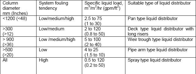
What should be verified is the evenness homogeneity of the liquid distribution m3hr of liquid per m2 of section at different areas and at least at nominal and minimum flow rate. In practice this is not achievable. Selectionof the distributortype dependingon above mentioned criteria.
The equation for flow through an orifice Eq. Determine Process Operation Variables Assumed feed rate composition purity of distillate and bottoms and the quality of the feed are known. For modern baffle plate distributors however this is not appropriate because the liquid is delivered to the packing in form of drip lines rather than drip points.
Volumetric flow rate 0234499 CumSec 3. Liquid distributors are a key component to optimal performance in packed distillation columns. 2 below governs the design of the distributor.
This means that flow is proportional to the square root of liquid head. In industrial process equipments liquid- liquid mixtures are produced by essentially two different mechanisms. Figure 3 shows the result of such a calculation for a trough with a width of b 100 mm for various flow velocities as a function of the liquid head h.
A the liquid is distributed from holes or slots and these must be large enough not to block b the distributor will not be perfectly level c space must be allowed for the passage of vapor and d process flexibility turndown is generally required. According to Bernoullis equation total head at a ny given point in liquid unde r motion is the sum of pressure velocity and elevation heads. The liquid outlet for this GLS is designed with the objective to prevent any entrainment of the incoming gas with the liquid.
8 Can employ a high concentration slurry as scrubbing liquid. 6 The following recommendations for the minimum liquid level h min in distributor troughs can. Operating Principles The incoming gas is accelerated to a high velocity at the scrubbers throat where it comes into contact with the scrubbing.
Let us straight away get to the steps for sizing a Perforated Pipe Liquid distributor. 1 Sizing the liquid outlet nozzle. A distributor with a side hole q80 and pipe guidance system creates the best distribution pattern where empty spaces are at a minimum.
6 Simple open design has low potential for build-up and pluggage. Determination the principle liquiddistribution. Indeed perfect distribution is not necessary.
Together with the head h o it allows the flow velocity at an outlet u o and thus the number of outlets required to be determined in distributors with liquid discharge or overflow. Perform overall material and component balances to determine the compositions of the distillate and bottoms. Detailed information about the TUMWelChem Cell Model is presented in Hanusch et al.
A Mixing of the phases in either purpose- built equipment mechanical mixers static mixers where pressure energy is applied to increase the surface free en- ergy of the fluids to produce droplets. A typical liquid head level in a v-notch distributor is 13in 2575mm over the entire operating range while a more standard orifice distributor will maintain a head of 312in 75300mm. Initially set the pipe size of the pipe distributor same as the pipe size feeding the pipe distributor Step 2.
Liquid distribution in the packing is estimated in dependence of the liquid distributor design. A crucial parameter in the design of a distributor is the liquid load uL required for the separation process. Graphical Determination of a Distillation Column Design Step 1.
The usual equation for flow through orifices is. Considering 20 safety factor HETP 0. 7 Temperature and corrosion resistant construction is available.
Of for The liquiddistributor designfollows four basicsteps. Both Metric units and USC units have been provided in the methodology. So for example a turndown of 41 would translate into an increase of 1600 in liquid elevation above a hole.
My experience is that such tests are essential. Molar flow rate 00094 KmolSec 2. A distributor with a base hole q60 generates a concentrated area below the trough.
Find the required pressure drop ΔP o across the distributor holes by multiplying the greater of E k or ΔP p by 10. O Contents solidsor tendency fouling. 800-231-0077 14211 Industry Street Houston TX 77053 TEL.
Of Hydraulic designof drip points. A distributor with a free overflow q 40 only saturates the line between the trough with water.

Liquid Distributors Importance Part 2 Mach Engineering

Importance Of Liquid Distributors Part 1 Mach Engineering

Column Internals Explained Part 2 Separation Technologies
Column Internals Explained Part 2 Separation Technologies
2

Orifice Trough Type Liquid Distributors Mach Engineering
2

Importance Of Liquid Distributors Part 1 Mach Engineering
0 comments
Post a Comment